Why should we learn LED panel assembly technology?
With the popularity of LED panels, They have become common in commercial displays., stage performances, conference rooms and press conferences. Whether you're an engineer, event planner, or DIY enthusiast, like mount an LED panel has become essential. This tutorial can help you purchase LED panel modules and accessories and assemble the panel.
Today, we will use the P2.5 LED panel common for indoor environments, for example.
Preliminary planning stage
Determine usage requirements
- Clearly define the purpose: do I use an indoor LED panel/outdoor LED panel? Advertising in a shopping mall (high brightness) or a conference room (high resolution)?
- Basic parameters: Select the resolution according to the viewing distance (P1.2-P2.5 for short distance, P3-P10 for long distance)
Size calculation
- Formula: Length = distance between points × number of points (e.g., distance between points 2.5 mm, 16 points = 40 cm)
- Screen composition: Number of modules = total area ÷ size of a single module (e.g., a 960 x 800 mm screen uses 15 modules of 320 x 160 mm)
Basic configuration
- Power supply estimate: Calculate according to the specifications of each module supplier. For example, the internal P2.5 module I am using today is a 200W power supply with 6 modules.
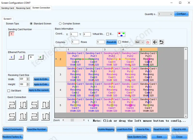
- Control system: Select according to synchronous/asynchronous requirements (e.g. Nova control system).
During the planning phase, the installation environment and budget should be prioritized. Simple rectangular screens are the easiest to implement.
Preparation of main material (taking the indoor P2.5 screen size of 960 x 800 mm as an example)
Display components
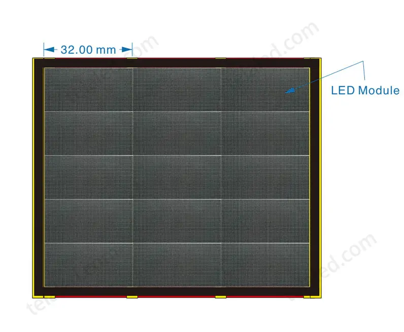
- LED Modules:
Select the number of modules according to the screen size. A width of 960 mm consists of 3 modules; a height of 800 mm consists of 5 modules.
Thus, 15 modules of 320 x 160 mm form a screen of 960 x 800 mm. - Lamp type: SMD Surface mount is commonly used for indoor displays, and COB/GOB (waterproof is best) can be selected for outdoor screens.
- Control system: Nova/Lingxingyu and other brands. The synchronous system needs to be equipped with a sending board + receiving board.
Power system
- Power supply configuration:
5 V (volts) 40 A (amps) 200 W (watts).
Power supply calculation formula: According to the information provided by the module manufacturer, a 200W power supply can support 6 internal P2.5 modules. This allows us to calculate how many power supplies are needed for this display screen. Number of modules/6 = 15/6≈3 (Typically, for a power supply with the same power, the number of external modules is smaller than the number of internal modules.) - Number of power supplies: 3
Thus, the power of the entire screen can also be calculated.
Screen power calculation: power supply power * number of power supplies
Theoretical screen power: 200W (watts) * 3 = 600W (watts) - Wire Specification: Use power cables above 0.75mm² (600W screens select 3 x 0.75mm² cables). Combining with the load capacity of the wire, according to the power of the screen, determine the specification of the main line to be used.
| Number of conductor cores / standard cross section | Outer diameter approx. | Recommended load (less than) | Nominal voltage |
| 3*0.3mm² | 5.3mm | 600W | 300/300V |
| 3*0.5mm² | 6.1mm | 1000W | 300/300V |
| 3*0.75mm² | 6.5mm | 1500W | 300/500V |
| 3*1.0mm² | 7.0mm | 2000W | 300/500V |
| 3*1.5mm² | 8.3mm | 3000W | 300/500V |
| 3*2.5mm² | 9.0mm | 5000W | 300/500V |
| 3*4.0mm² | 11.2mm | 8000W | 300/500V |
| 3*6.0mm² | 12.3mm | 12000W | 300/500V |
| 3*10.0mm² | 20000W | 300/500V |
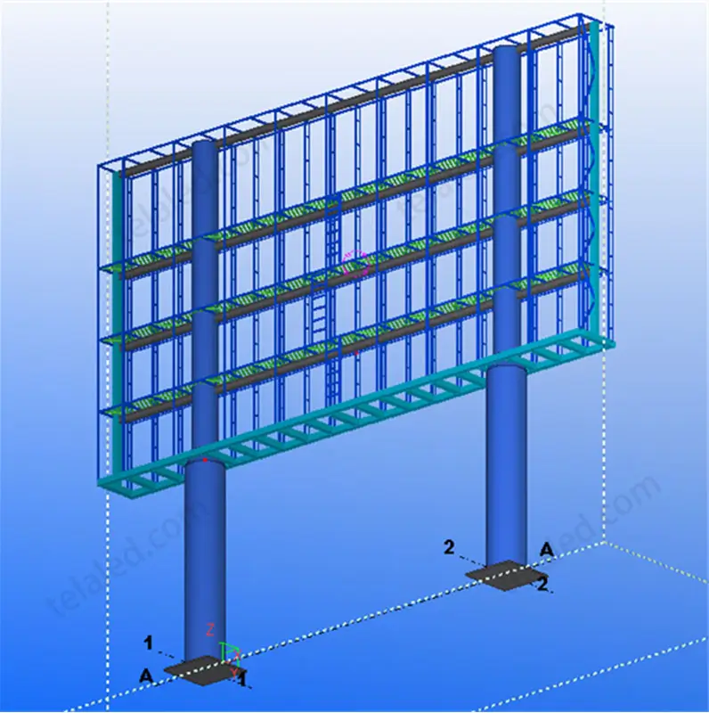
- Structure
We know the size of the display screen is 960mm x 800mm. We will use the main keel + secondary keel + frame structure to build this main structure. - Screen thickness
The main keel adopts 40 x 40 mm square tube, the secondary keel adopts 20 x 40 mm square tube, and the upper, lower, left and right frames adopt 30 x 30 mm square tube.
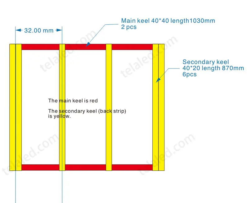
Therefore, the thickness of the entire screen structure is: 40 + 20 + 30 = 90 mm - Main keel
How to calculate the length of horizontal square tube?
The width of the screen is 960mm, plus the thickness of the left and right frames (we used 30×30 square tubes), considering thermal expansion compensation and construction error, reserving 10mm.
Therefore, the length of the horizontal square tube: 960+30+30+10 = 1030 mm.
One horizontal and one horizontal, so the main keel, a 40x40 square tube, 1030mm long, requires 2. - Secondary keel
The longitudinal secondary keel, i.e., the rear support bar. We use the same algorithm as above to calculate its length: 800 + 30 + 30 + 10 = 870 mm.
For the number of secondary fins, we added one on each side for fine-tuning. Therefore, when calculating the number, add 3 to the number of modules to get the actual number of secondary fins required.
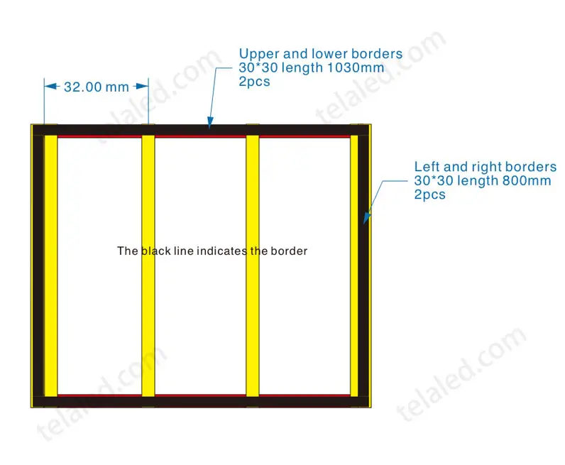
We have 3 modules in a horizontal row, so we need 3 + 3 = 6 secondary fins. - Screen structure
We used 30 x 30 square tubing for the frame, so the upper and lower frames: 1030 x 2
Left and right structures: 800 x 2 - Screen edges
In order to make the screen beautiful and generous, as well as protect the edges, we generally use stainless steel for the edges of the screen, adjusting the outer dimensions of the screen according to the above dimensions.
Tip: It is recommended to add 5% of extra modules and wires at the time of purchase, and prioritize power supplies from top-tier brands (such as Mean Well) to improve stability.
Detailed assembly process (how to assemble an outdoor & indoor LED panel)
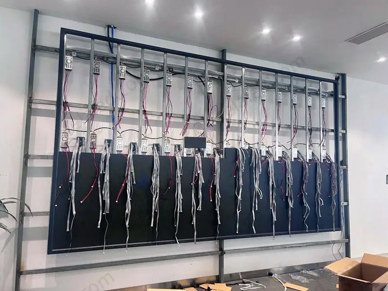
Construction of the basic structure
- Main keel installation: First, use 40×40 square tubes to build a horizontal support (1 on top and 1 on the bottom).
- Secondary keel attachment: vertically install 20 40x60 square tubes as support (6 in total, evenly spaced).
- If the screen will be used outdoors, you also need to consider waterproofing. A rainproof cover should be designed into the frame to protect the back of the screen and prevent rain from causing a short circuit.
Module installation
- Magnetic Fixation: Fix the LED module to the frame according to the design drawing to ensure a perfect splice.
- Direction check: The direction of the arrows on all modules must be consistent.
Power and control connection.
- Parallel power connection: connect one power supply for every 6 modules, using 5V/40A specifications.
- Network cable layout: sending board → receiving board → cascade module (single network cable load ≤ 650,000 pixels).
Safety Tips: It is recommended to turn off the entire process. After connecting, test one module first and then turn on all of them.
Debugging and acceptance
Basic debugging
- Single-point lighting test: Turn on each module in turn to check if it emits light normally.
- Color Consistency: Reproduce images with pure colors (red/green/blue/white) and check for abnormal lamps
Joint system debugging
- Control board matching: Confirm whether the control system of brands such as Nova is charging normally
- Playback Test: Switch videos/photos and check if the refresh rate is ≥3840Hz without flickering
Acceptance criteria
- Functionality: No dead lights (≤3/㎡ allowed), no screen distortion
- Safety acceptance: Power supply temperature ≤60°C, no cable overheating
Tip: It is recommended to keep aging test records for 72 hours and remotely synchronize with the manufacturer's technical support
Post-installation optimization
Optimizing system settings
- Adjust the brightness according to the ambient light. It is recommended to use 200-800 cd/㎡ indoors and 5000-8000 cd/㎡ outdoors.
- Set the timer to turn on and off, extending the life of the LED and saving energy (can be set by the control system).
Content management optimization
- Adopt smart split-screen mode to support multiple windows and play different contents (video + text + images, etc.) simultaneously.
- Adapt to horizontal and vertical screen switching to meet the display requirements of different scenarios.
Remote operation and maintenance configuration.
- Link the remote monitoring system to monitor temperature, humidity, voltage and other parameters in real time.
- Open the manufacturer's technical support to facilitate quick handling of dead lights, color difference and other problems.
Tip: It is recommended to clean the heat dissipation holes once a month to prevent dust accumulation and affect heat dissipation.
Professional TELALED support
Full technical support
- Preliminary planning: Provide customized solutions according to application scenarios (shopping malls/stages/stadiums, etc.), supporting the design of special-shaped screens
- Installation Guidance: Engineers provide remote or on-site guidance and installation specification manuals.
After-sales guarantee
- Warranty Service: 3 years warranty + lifetime maintenance for the whole machine, 2-hour response for emergencies
- Spare parts support: 5% of spare parts are provided with the products, and the 24-hour spare parts arrival rate is 90%
Operation and maintenance service
- 24/7 support: multi-channel technical response via phone/email/online chat
- Remote monitoring: real-time display of temperature, humidity and other operating data on the screen
Key Advantages: 20 years of industry experience spanning over 102 countries, over 10,000 quality assurance projects
If you have any questions about how to assemble LED panels for indoor and outdoor environments, consult our professional engineers.